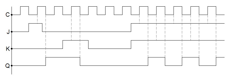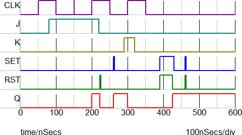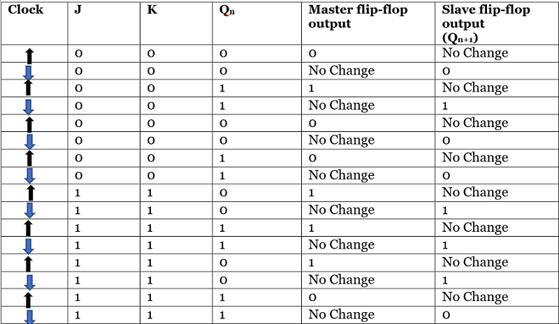
 Circuitry in a digital clock takes the output of a 65,536 Hz Oscillator and divides it down to 1 Hz (1 pulse per second). A D flip flop can be made to operate in a toggle mode (divide its CLOCK input frequency by two) by adding an external Inverter gate and making the appropriate connections.
  A JK flip flop can be made to operate as a D flip flop by adding an external Inverter gate and making the appropriate connections. (If you’re not sure, refer to the Part 2 of Lab 7 manual.) Questions/Report Record the propagation delay (found in the tco tab) at the Q output with respect to the clock input:ĥ) Now you are ready to assign Pin Names and Numbers as shown in the following Table.Ħ) Save and compile the design again before programming. The CLK period should be set to 100ns.Ĥ) After a successful simulation, choose the Timing Analyzer Tool from the Processing menu. Set the following parameters in the Simulation waveforms: Grid Size=100ns End Time=2µs. Open a New Block Diagram/Schematic file and draw the circuit for the D flip flop.įigure 11-2 Frequency Divider/Counter Circuits using JK Flip Flops.ģ) After a successful compilation, open a new Vector Waveform file and construct the input waveforms: CLK. Assign the project name Lab 11 _1, assign Cyclone II for the device family, and select the EP2C35F672C6 chip in the Family & device settings.
And create a new project name under the directory C :\altera\91sp2\quartus\ your last name \Lab 11. Part 1: Construction and Simulation of a D Flip Flop Circuit The circuit will then be tested and its operation verified on the DE-2 board. Using Quartus II adder circuits will be constructed using the Graphic Editor.Asynchronous inputs override synchronous inputs when there is a conflict. They also have asynchronous inputs that are level sensitive and independent of the clock input.Flip flops have synchronous inputs that are sampled on the positive or negative going edge of the clock input.Flip flops are different from combinational logic in that their output depends on past and present input states.

This experiment will cover the operation of the two types of edge triggered flip flops: D and JK. The DE-2 board will be programmed with JK flip flops configured as a frequency divider/counter. To show how flip flops can be used as frequency dividers/counters. A simulation waveform will be constructed and used to exercise the inputs and observe the resulting output. To investigate the behavior of a D flip flop with the Altera Quartus II program. 5 Part 2: Construction of a 5 stage JK Flip Flop Frequency Divider/Counter Circuit. 4 Part 1: Construction and Simulation of a D Flip Flop Circuit.


 0 kommentar(er)
